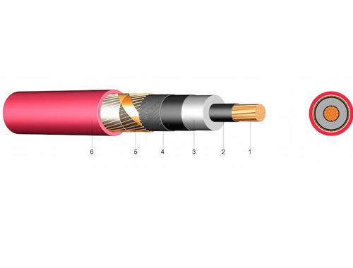

| Description, Nominal Voltage & No. Cond. x cross-sec. mm2 | Operation Voltage max. | Insulation Thickness mm | Shield cross-sec. mm2 | Outer Dia. mm |
Copper Weight kg/km | Alu Weight kg/km |
Weight ca. kg/km |
AWG |
| NA2XS(F)2Y 6/10kV 1X35 rm/16 | 12 | 3.4 | 16.0 | 26.0 | 182.0 | 102.0 | 780.0 | 2 |
| NA2XS(F)2Y 6/10kV 1X50 rm/16 | 12 | 3.4 | 16.0 | 28.0 | 182.0 | 145.0 | 850.0 | 1 |
| NA2XS(F)2Y 6/10kV 1X70 rm/16 | 12 | 3.4 | 16.0 | 30.0 | 182.0 | 203.0 | 980.0 | 2/0 |
| NA2XS(F)2Y 6/10kV 1X95 rm/16 | 12 | 3.4 | 16.0 | 31.0 | 182.0 | 276.0 | 1080.0 | 3/0 |
| NA2XS(F)2Y 6/10kV 1X120 rm/16 | 12 | 3.4 | 16.0 | 32.0 | 182.0 | 348.0 | 1150.0 | 4/0 |
| NA2XS(F)2Y 6/10kV 1X150 rm/25 | 12 | 3.4 | 25.0 | 34.0 | 283.0 | 435.0 | 1280.0 | 300 kcmil |
| NA2XS(F)2Y 6/10kV 1X185 rm/25 | 12 | 3.4 | 25.0 | 36.0 | 283.0 | 537.0 | 1420.0 | 350 kcmil |
| NA2XS(F)2Y 6/10kV 1X240 rm/25 | 12 | 3.4 | 25.0 | 38.0 | 283.0 | 696.0 | 1630.0 | 500 kcmil |
| NA2XS(F)2Y 6/10kV 1X300 rm/25 | 12 | 3.4 | 25.0 | 40.0 | 283.0 | 870.0 | 1950.0 | 600 kcmil |
| NA2XS(F)2Y 6/10kV 1X400 rm/35 | 12 | 3.4 | 35.0 | 44.0 | 394.0 | 1160.0 | 2350.0 | 750 kcmil |
| NA2XS(F)2Y 6/10kV 1X500 rm/35 | 12 | 3.4 | 35.0 | 47.0 | 394.0 | 1450.0 | 2780.0 | 1000 kcmil |
| NA2XS(F)2Y12/20kV 1X50 rm/16 | 24 | 5.5 | 16.0 | 33.0 | 182.0 | 145.0 | 920.0 | 1 |
| NA2XS(F)2Y12/20kV 1X70 rm/16 | 24 | 5.5 | 16.0 | 34.0 | 182.0 | 203.0 | 1030.0 | 2/0 |
| NA2XS(F)2Y12/20kV 1X95 rm/16 | 24 | 5.5 | 16.0 | 36.0 | 182.0 | 276.0 | 1140.0 | 3/0 |
| NA2XS(F)2Y12/20kV 1X120 rm/16 | 24 | 5.5 | 16.0 | 37.0 | 182.0 | 348.0 | 1250.0 | 4/0 |
| NA2XS(F)2Y12/20kV 1X150 rm/25 | 24 | 5.5 | 25.0 | 39.0 | 283.0 | 435.0 | 1320.0 | 300 kcmil |
| NA2XS(F)2Y12/20kV 1X185 rm/25 | 24 | 5.5 | 25.0 | 41.0 | 283.0 | 537.0 | 1570.0 | 350 kcmil |
| NA2XS(F)2Y12/20kV 1X240 rm/25 | 24 | 5.5 | 25.0 | 43.0 | 283.0 | 696.0 | 1780.0 | 500 kcmil |
| NA2XS(F)2Y12/20kV 1X300 rm/25 | 24 | 5.5 | 25.0 | 45.0 | 283.0 | 870.0 | 2100.0 | 600 kcmil |
| NA2XS(F)2Y12/20kV 1X400 rm/35 | 24 | 5.5 | 35.0 | 48.0 | 394.0 | 1160.0 | 2480.0 | 750 kcmil |
| NA2XS(F)2Y12/20kV 1X500 rm/35 | 24 | 5.5 | 35.0 | 52.0 | 394.0 | 1450.0 | 2900.0 | 1000 kcmil |
| Description, Nominal Voltage & No. Cond. x cross-sec. mm2 | Operation Voltage max. | Insulation Thickness mm | Shield cross-sec. mm2 | Outer Dia. mm |
Copper Weight kg/km | Alu Weight kg/km |
Weight ca. kg/km |
AWG |
| NA2XS(F)2Y18/30kV 1X50 rm/16 | 36 | 8.0 | 16.0 | 37.0 | 182.0 | 145.0 | 1250.0 | 1 |
| NA2XS(F)2Y18/30kV 1X70 rm/16 | 36 | 8.0 | 16.0 | 38.0 | 182.0 | 203.0 | 1500.0 | 2/0 |
| NA2XS(F)2Y18/30kV 1X95 rm/16 | 36 | 8.0 | 16.0 | 40.0 | 182.0 | 276.0 | 1700.0 | 3/0 |
| NA2XS(F)2Y18/30kV 1X120 rm/16 | 36 | 8.0 | 16.0 | 42.0 | 182.0 | 348.0 | 1800.0 | 4/0 |
| NA2XS(F)2Y18/30kV 1X150 rm/25 | 36 | 8.0 | 25.0 | 43.0 | 283.0 | 435.0 | 2050.0 | 300 kcmil |
| NA2XS(F)2Y18/30kV 1X185 rm/25 | 36 | 8.0 | 25.0 | 45.0 | 283.0 | 537.0 | 2150.0 | 350 kcmil |
| NA2XS(F)2Y18/30kV 1X240 rm/25 | 36 | 8.0 | 25.0 | 47.0 | 283.0 | 696.0 | 2400.0 | 500 kcmil |
| NA2XS(F)2Y18/30kV 1X300 rm/25 | 36 | 8.0 | 25.0 | 50.0 | 283.0 | 870.0 | 2700.0 | 600 kcmil |
| NA2XS(F)2Y18/30kV 1X400 rm/35 | 36 | 8.0 | 35.0 | 53.0 | 394.0 | 1160.0 | 3200.0 | 750 kcmil |
| NA2XS(F)2Y18/30kV 1X500 rm/35 | 36 | 8.0 | 35.0 | 56.0 | 394.0 | 1450.0 | 3550.0 | 1000 kcmil |
|
|||
|
|
||
| Code-Designation for Power Cables with PVC or XLPE Insulation
|
|||||||||||||||||||||||||||||||||||||||||||||||||
|
|||||||||||||||||||||||||||||||||||||||||||||||||